Memory segmentation
Once upon a time, Intel introduced the 8086 microprocessor, which gave birth to the X86 family of microprocessors. It was a 16 bit processor. This means that all registers are 16 bits wide and officially, the memory bus is too. In theory, that would allow for a memory address space of only 65.535 (2^16) bytes. Even back then, this was too limited for any practical use.
Fortunately, Intel provided a 20-bit memory bus instead, which allowed for a memory address space of 1 MB (2^20). Less fortunately, you can’t store 20 bits in a 16 bit register to reference that memory. To overcome this, a segmented memory model was invented where memory addresses were split up in two parts: the base and the offset. The base was stored in a segment register. Offsets are specified explicitely when referencing memory, or by using a pointer register which relates to a specific segment (more about that later). In 16 bit programming, that is the only way to reference memory. It is written as (segment:)offset and if segment is omitted, the default is assumed for the current context. These pairs directly map to physical memory and this mode is called “real mode”. Even today, X86 CPUs start in real mode to stay compatible and this means we need to know about it for our bootloader.
Along with the 80286 when it was introduced, a second operation mode called “protected mode” was added which worked with a Global Descriptor Table. This data structure allowed for protection levels and size specification of each memory segment by using descriptors. In this mode, the segment registers contain so called segment selectors which point to an entry in the GDT instead. Once we move to protected mode for our kernel in the final part, the GDT will be explained in more detail.
Registers
Registers are tiny circuits that can be used to store and retrieve data. An X86 CPU has many registers which can be divided into three main categories: data registers, address registers and status registers.
With the introduction of the 32 bit 80386 CPU came 32 bit registers. They replaced their 16 bit predecessors and the “E” (extended) prefix was added to their names (except for the segment registers, which are only there for compatibility). So, the 16 bit AX register became EAX, etc. The 16 bit (and even 8 bit) parts are still accessible, as will be described below, but even though we start off in 16 bit mode for our bootloader, we will use the 32 bit names throughout these series for legibility purposes.
Data registers
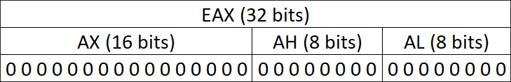
In an X86 CPU, there are eight data registers (EAX, EBX, ECX, EDX, ESI, EDI, EBP and ESP), of which the first 6 are general purpose registers that can be used as input and output for operations. The last 2, EBP and ESP, are reserved for other use. They are 32 bits (4 bytes) wide and some of them can be accessed as only the least significant 16 bits, or two blocks of 8 bits within the most significant 16 bits:
Here is a list of all general purpose data registers with their 16 and 8 bit counterparts and reserved used if applicable:
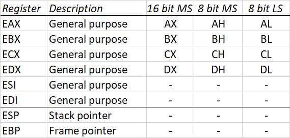
The last two, as mentioned earlier, ESP and EBP, are reserved for stack allocation purposes and can not be used for anything else (although modern compilers allow you to eliminate the need for EBP and free it up for general purpose use). This leaves 6 general purpose data registers for use during operations.
Address registers
In this category we can distinguish segment registers (CS, DS, SS, ES, FS and GS), pointer registers (EBP, ESP and EIP) and index registers (ESI and EDI). In real mode, the segment registers contain the base address of a memory segment (for instance, CS contains the base address for executable code in memory, DS for data) and together with the instruction pointer (IP in 16 bit), the exact location of executable code can be referenced through CS:IP.
The ESI/EDI (source and destination index respectively) registers are used to point to memory locations in DS and ES respectively. Incrementing ESI allows you to quickly access consecutive memory locations, whereas EDI is used in string operations in combination with the ES register.
Status registers
A specialized register called EFLAGS is reserved to contain various status flags. These flags are typically set by an operation and checked in a subsequent operation, but can also be used to conditionally jump to another block of code, depending on one of these flags.
To our story, the most interesting flags are the following:
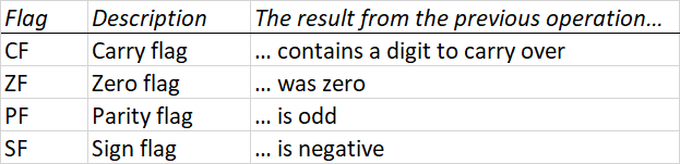
The EFLAGS register can be pushed to the stack by using the pushfd instruction and it can be updated by the topmost value on the stack by using the popfd instruction.
A note on endianness
When storing data into a single byte, everyone agreed that (from left to right) the first bit represents the highest number (2^7) and the last bit represents the lowest number (2^0). These are called the most significant bit and the least significant bit respectively. As long as we stay within a single byte, this never poses any problems and the order within the byte always stays the same.
However, when we need to store multi-byte data, there is a potential difference across systems. For instance, the 32 bit integer 0x12345678 must be stored across 4 bytes, do we store it as: [0x12, 0x34, 0x56, 0x78] or as [0x78, 0x56, 0x34, 0x12]? Whilst the former looks more natural to us, on X86 it’s actually stored like the latter. This is called “little endian” because the smallest number (the last 8 bits of the 32 bits, representing the lowest value 2^0 through 2^7) is stored at the first memory address and the rest follows. The opposite is called “big endian”, because the biggest number (the first 8 bits of the 32 bits, representing the highest value 2^24 through 2^31) is stored at the first memory address instead.
Fun fact: the terms “little endian” and “big endian” actually refer to the conflicting ideologies described in Gulliver’s Travels around the practice of breaking eggs: which end of the egg do you break first?
Time for part 3!