With the hardware installed, we are now ready to create separate networks for our DMZ and IoT devices, configure our managed switch to use these networks on specific ports, create a separate wireless network for these devices and also configure the firewall to block unwanted traffic between them.
Isolating the networks
Creating separate networks for IoT and DMZ
First, we define the actual networks within Unifi for these devices. The idea is that we can use these network definitions for firewall rules and port assignments on our switch later.
The original LAN network was subnetted as 192.168.1.0/24. I thought it would be good idea to match the subnet and the VLAN id, but this is entirely up to you.
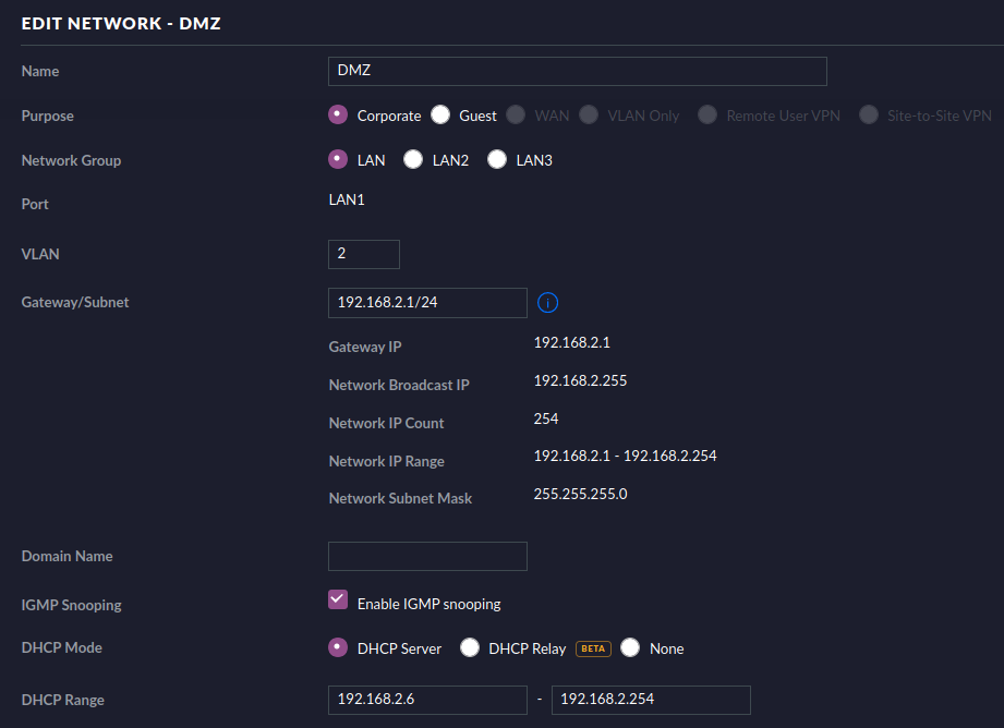
So, for the DMZ network, I decided to use subnet 192.168.2.0/24 with VLAN id 2:
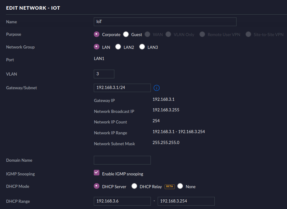
And for the IoT network, I used 192.168.3.0/24 with VLAN id 3:
Assigning port profiles on the managed switch
Now, the power of all this comes from the fact that when you assign a port on a managed switch to use a specific network, devices physically connected to that port will be restricted within that network and automatically receive an IP address and VLAN id that matches this network.
You can configure this for a port easily through the UI:
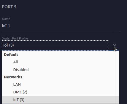
So, a device connected to port 5 on my switch will be on the IoT network and obey the configuration, routing and firewall rules defined for that network.
An overview of my final port configuration:
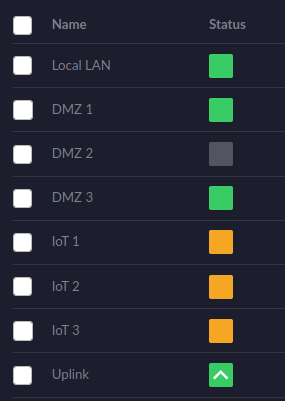
Port 8 is the uplink to the USG. Port 1 is the Local LAN port to which my existing unmanaged switch is connected. Port 2 through 4 are assigned the DMZ profile and port 5 through 7 are assigned the IoT profile.
Creating a separate wireless guest network
Of course we have only covered physically connected devices to the network so far, but this VLAN principle can easily be extended wirelessly. We simply have to create a new wireless network that uses the same VLAN id and then connect the devices we want to use this VLAN id to this network instead.
Again, this is very easy to do within Unifi:
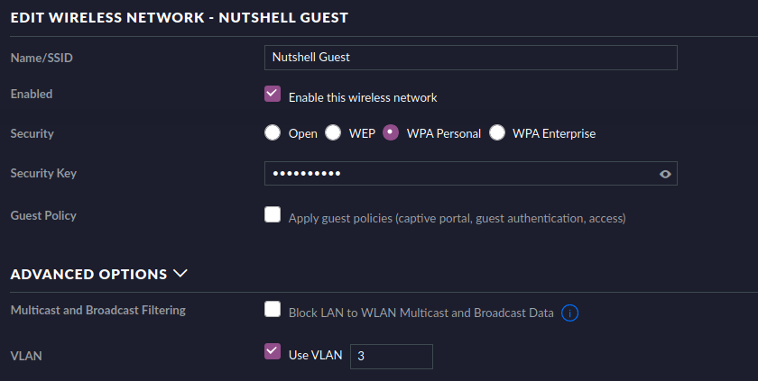
I named the network Guest because this is also the network I tell guests to use for their phones, automatically isolating them from my local LAN in the process.
Word of caution: if your access points are connected physically to a different (V)LAN than this new wireless guest network, make sure that the port on the switch that your access points are ultimately connected to (maybe through another switch) does not have a specific switch port profile set but instead is set to All. If a specific profile is set for this port that does not include the (V)LAN of your access points, wireless clients will not be able to get an IP address through DHCP.
Configuring the firewall
By default, all networks will be able to talk to each other. We need to configure the firewall to block access from the new networks to our local LAN network.
Rules are applied from top to bottom, meaning if a packet is dropped by a rule, additional rules that also match this packet will have no effect anymore. So, make sure the order of rules is correct.
Additionally, packets should be dropped as early as possible, so that resources are not wasted on them in later stages. Since the rules we want to define are related to our internal networks, the earliest point we can define them is LAN IN (these are incoming packets on the USG’s LAN device).
Defining firewall rules is very easy. For instance, dropping traffic from the IoT network to the local LAN looks like this:
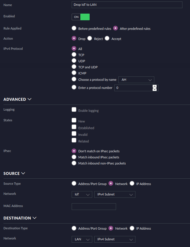
The “Advanced” section also allows you to select states. Established and related packets are important because you still want answers to come back to the originating device, regardless of its network. For instance, if I connect to a Raspberry PI or my NAS within the DMZ network from the local LAN, I need established and related packets to be accepted back for communication to take place.
So, in its most basic form, this overview shows all the required rules to accept established and related packets, while blocking everything else:
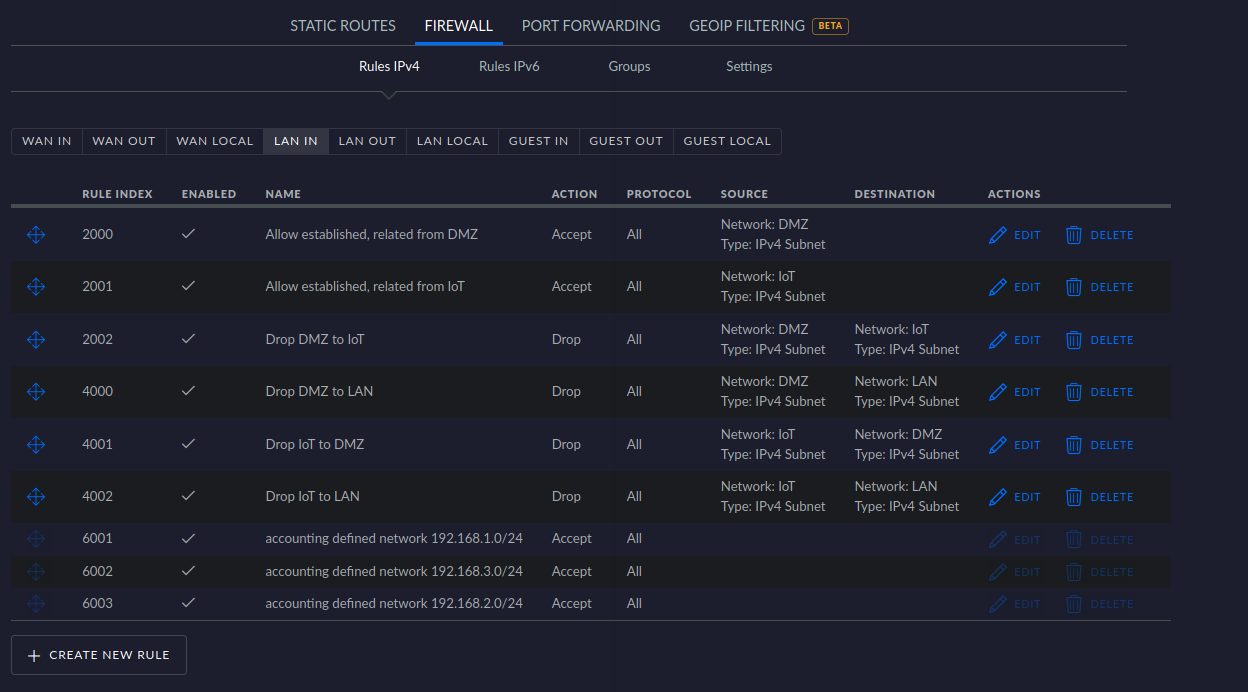
The bottom three rules are predefined by Unifi, allowing all traffic between these networks. So, if a packet is not dropped by a rule above it, it will be allowed by default.
The four rules above these predefined rules drop all traffic from DMZ to IoT and LAN and also from IoT to DMZ and LAN. This isolates these networks from the LAN network.
The top two rules allow established and related packets to come back to the LAN network so we can still communicate with devices in the isolated networks from the LAN.
Conclusion
We now have three separate networks and a separate wireless network that are isolated from the other devices on our LAN. This means that if an IoT device or a server in the DMZ gets compromised, the rest of the network is not immediately exposed.
While there are obviously many ways to accomplish this, I hope sharing my experiences helps someone who is considering upgrading their network or runs into issues with any of these subjects touched.