To move data between registers, we already learned that we need to enable the source register on the bus, then set the target register so the value gets stored there, then unset the target register to disconnect it from the bus and then disable the source register. The order in which this happens is very important, because doing it in any other way will cause the wrong value to be stored in the target register.
To be able to synchronize this and everything else going on in a computer, the CPU has something called a clock which basically turns on and off a single bit at extremely fast speeds (the clock speed). This bit is the input electricity to everything else we described earlier and is most commonly generated by an oscillator, which pulses at a specific frequency. It works by using the piezoelectric properties of a quartz crystal that generates an electric pulse when mechanically stressed and bends when electrically stressed.
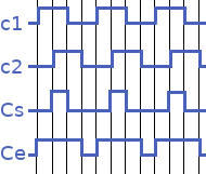
The clock itself is only a single bit (c1 in the image above). If we would use that as the pulse for both the enabler and the setter, this will become a problem if the clock pulse goes to 0 because we can’t guarantee, for instance, that the setter of a target register is switched off before the enabler of the source register is. As such, it may be that we end up with the wrong value in the target register. To solve this, a second signal c2 is derived from the clock, called the delayed clock which is delayed approximately a quarter of a cycle. With a combination of these signals, we can do something interesting.
Using an OR gate that takes the two signals as an input, we can derive a signal Ce that is only 1 whenever either c1 or c2 is 1 (meaning an extended period of time). We also derive signal Cs that comes from an AND gate with the signals as input, that is only 1 whenever both c1 and c2 are 1 (meaning a shortened period of time). Cs is guaranteed to fall within the period of Ce, so we can use that to our advantage: we hook up Ce as the so called “clock enable” bit, used as the pulse for the enablers of our registers and signal Cs as the “clock setter” bit, used as the pulse for the setters of our registers. This will ensure that the register is unset before its source is disabled.
This construct forms the heartbeat of our computer.
Machine code and the instruction set
A CPU has a specific set of instructions that it “knows” and from which more complex operations can be carried out. This is known as the instruction set. For instance, an instruction could be to load data from a specific memory address, or store some data there. Another instruction might be to carry out an ALU operation or jump to an entirely different place in memory and start executing instructions there.
All instructions in the CPU’s instruction set are in machine code, which is nothing more than a string of bits, each unique value representing an instruction. Whatever high level language you use to write code, ultimately it gets translated to machine code because that’s the only thing a CPU can work with.
The instruction a CPU should carry out next is stored in the instruction register (IR) and the memory address of the instruction to load into IR after that is stored in the instruction address register (IAR).
Instruction cycle
We already know that even the slightest bit of complexity requires more than one instruction, so there must be some way for the CPU to carry out this sequence of instructions to do something interesting. There is, and this is called the instruction cycle. This cycle runs continuously from the moment the computer is powered on to the moment it is powered off. It is also known as the fetch-decode-execute cycle, because that is literally what it does.
The CPU fetches an instruction from RAM (the address of which resides in IAR), puts it in IR, increments IAR so during the next instruction cycle we will have another instruction, and executes the instruction in IR. This process is repeated many million times a second.
The moment the computer is powered on, a predefined value (based on the architecture) is loaded into the IAR which typically points to a program in ROM that boots the computer and loads the operating system. Whenever you execute your own program, it is loaded into memory for execution. It is eventually up to the operating system to determine when your program actually gets executed, but once it does, it will follow the rules described above.
Wrapping up
What we have discussed in the last couple of chapters are the basics of how computers work internally. In my opinion it is interesting to know in general and will also help you if you only work in high level languages, because it may help understand more technical concepts like memory usage and performance optimization better. But I think it helps even more when you want to do more low level stuff, like working in assembly. Moving data between registers and jumping around suddenly makes a lot more sense.
Essentially, everything is about electricity and whether or not that electricity is passed through components. These components by themselves are simple, but combining them in the right way makes for more interesting possibilities. Then, it is just a matter of timing.
I hope you found this information useful. Feel free to send me some feedback if you feel anything can be improved!
If you want to move on to creating a basic X86 kernel, which all this started with in the first place, you can find it here!